
< Previous | Contents | Next >
Section 2 Test Specimens and Testing Procedures
201. General
1. Application
(1) Test specimens and mechanical testing procedures for materials are to comply with the require- ments of this Section, unless otherwise specially provided in each Section.
![]()
![]()
(2) Where test specimens and testing procedures differing from those prescribed in this Section are used, they are to be approved by the Society. See Guidance
2. Testing machine
(1) The testing machines used for the tests relative to this Chapter are to be managed by competent personnel on machines.
![]()
![]()
(2) Tension/compression testing machines are to be calibrated in accordance with ISO 7500-1 or other recognised standard. See Guidance
![]()
![]()
(3) Impact testing machines are to be calibrated in accordance with ISO 148-2 or other recognised standard. See Guidance
(4) The accuracy of tensile test machines is to be within ±1%
3. Selection of test specimens
(1) The test specimens are to be selected according to each requirement in this Chapter.
![]()
![]()
(2) Except where otherwise specified or agreed with the Surveyor, test samples are not to be de- tached from the material until being stamped by the Surveyor. See Guidance
(3) If test samples are cut from material by flame cutting or shearing, a reasonable margin is re- quired to enable sufficient material to be removed from the cut edges during final machining.
(4) The preparation of test specimens is to be done in such a manner that test specimens are not subjected to any significant cold working or heating.
(5) If any test specimen shows defective machining or defects having no relation to the substantial nature, it may be discarded and substituted by another test specimen.
202. Form and dimension of test specimen
1. Tensile test specimen
(1) Tensile test specimens are classified as standard test specimen and proportional test specimen as shown in Table 2.1.1 depend on the shape and dimension of test specimen.
Table 2.1.1 Kinds of tensile test specimen
Kind | Flat | Round | Pipe |
Proportional | R14B | R14A | R14B, R14C |
Standard | R1A, R1B, R5, R13B | R4, R8C, R10 | - |
![]()
![]()
(2) Tensile test specimens are to be of the forms and sizes given in Fig 2.1.1. See Guidance
![]()
![]()
(3) The gauge length may be rounded off the nearest 5 mm, provided that the difference between this length and is less than 10 % of .
![]()
Shapes | Kind | Type | Forms of specimen(1) | Size of specimen(2) | Materials to be applied |
Flat(3) | Proportional | R 14B |
| = = 25 mm = (4) ≅ = 25 mm | Rolled steels 3 mm thick or more, Aluminium alloy 12.5mm thick or less |
Standard | R 1A | = = 40 mm = 200 mm ≅ 220 mm = 25 mm | Rolled steel plates for boiler, Rolled steel plates for pressure vessel | ||
R 1B | = = 25 mm = 200 mm ≅ 212.5 mm = 25 mm | Rolled steels 3 mm thick or more, | |||
R 5 | = = 25 mm = 50 mm ≅ 60 mm = 15 mm | Rolled steel plates for pressure vessel | |||
R 13B | = = 12.5 mm = 50 mm ≅ 60 mm = 25 mm | Rolled steels less than 3 mm thick | |||
Round | Proportional | R 14A |
| = 5 (5) ≅ = 10 mm(6) | Rolled steels, Castings, Forgings, Spheroidal or nodular graphite iron castings, Copper alloy Aluminium alloy 12.5mm thick or more |
Standard | R 4 |
| = 14 mm = 50 mm ≅ 60 mm = 15 mm | Rolled steel plates for pressure vessel | |
R 10 | = 12.5 mm = 50 mm ≅ 60 mm = 15 mm | Rolled steel plates for boiler | |||
R 8C |
| = 20 mm = 25 mm | Grey iron castings |
![]()

![]()
![]()
![]()
![]()
![]()
![]()
![]()
![]()
![]()
Fig 2.1.1 Types and forms of tensile test specimens (unit : mm)
![]()
Shapes | Kind | Type | Forms of specimen | Size of specimen | Materials to be applied |
Pipe | Proportional | R 14B |
| = t 12 mm = ≅ + 2 = 25 mm | Steel tubes, copper and copper alloy pipes and tubes |
R 14C |
| = ≅ + is the distance between the grips | |||
NOTES: (1) The notations used are defined as follows. : Diameter, : Cross section, : Thickness, : Transition radius, : Width : External tube diameter, : Gauge length, : Plate thickness, (2) The both ends of the test specimens may be machined to such shapes as to fit the holder of the testing machine. (3) When the capacity of the available testing machine is insufficient to allow the use of test specimen of full thickness, this may be reduced by machining one of the rolled surfaces. (4) Gauge length (5) d (6) For nodular cast iron and materials with a specified elongation less than 10%, R | |||||

![]()
![]()
![]()
![]()
![]()
![]()
![]()
![]()
Fig 2.1.1 Types and forms of tensile test specimens (unit : mm)
(4) The manufacturers may use the test specimens approved by the Society, besides those specified
![]()
![]()
in (2). In this case, the elongation measured at the tensile tests is to be corrected by lowing formula See Guidance :
![]()
․ ․ ![]()
where:
![]()
= equivalent elongation for the proportional test specimens specified in (1) (%).
= actual measured elongation of test specimen (%).
![]()
= actual cross-sectional area of test specimen (mm ).
= actual gauge length of test specimen (mm).
the fol-
![]()
![]()
![]()
![]()
![]()
, = constants given in bellow in accordance with the kind of materials.
Constant Material |
|
|
Material 1 | 2.0 | 0.40 |
Material 2 | 2.6 | 0.55 |
NOTES: 1. Material 1 : For carbon and low alloy steels with a tensile strength not exceeding 590 N mm in the hot rolled, annealed, normalized or normalized and tempered conditions. 2. Material 2 : For carbon and low alloy steels in the quenched and tempered condition. 3. The values of a and b for other kinds of materials than Material 1 and Material 2 are to be as deemed appropriate by the Society. | ||
![]()
(5) The machine-finished parallel part of test specimens is to be uniform throughout the entire
length and the permissible variation (difference between the to be as specified in Table 2.1.2.
maximum and minimum values) is

Table 2.1.2 Permissible Variation (unit : mm)
Round specimen
Flat specimen with thickness equal to or
greater than 6 mm Flat specimen with thickness less than 6 mm
Nominal diameter (d)
Permissible variation
Nominal Thickness (t)
permissible variation
Nominal width (w)
permissible variation
Nominal Thickness (t)
permissible variation
Nominal width (w)
permissible variation
10 d<12 0.025 6 t<12 0.02 25 w<40 0.05 0.6 t<1.2 0.002 12.5 w<25 0.02
12 d<16 0.03 12 t<20 0.04 40 w 0.10 1.2 t<2.5 0.004 25 w 0.04
16 d 0.04 20 t 0.05 2.5 t<6 0.01
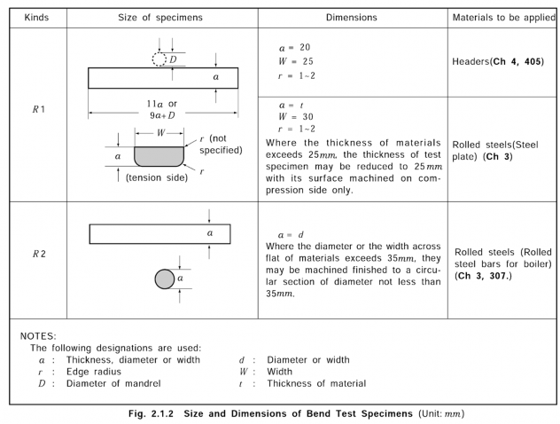
2. Bend test specimen
Bend test materials.
specimens are to be of size and dimensions given in Fig 2.1.2
according to the kind of

3. Impact test specimen
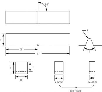
(1) Impact test specimens are to be provided in a set of three specimens, and the test specimens are to be machine finished to the forms and dimensions given in Fig 2.1.3 and Table 2.1.3
![]()
unless the section thickness of the product is less than 12 mm
(2) The notch is to be cut in a face of the test specimen which was originally perpendicular to the rolled surface, casting surface and forging surface according to the kind of materials. The posi- tion of the notch is not to be nearer than 25 mm to a flame cut or sheared edge.

Fig 2.1.3 Impact test specimen

Table 2.1.3 Dimensions of impact Test Specimens
Kinds Dimensions | Charpy V-notch test specimen | |
Length (mm) | 55 ± 0.6 | |
Width (mm) |
| 10 ± 0.11 |
Thickness (mm) |
| 10 ± 0.06 |
Angle of notch (mm) |
| 45 ± 2 |
Depth below notch (mm) |
| 8 ± 0.06 |
Root radius of notch (mm) |
| 0.25 ± 0.025 |
Distance of notch from end of test specimen (mm) |
| 27.5 ± 0.42 |
Angle between plane of symmetry of notch and longitudinal axis of test specimen (deg) | - | 90 ± 2 |
(3) Where the impact test specimens, having the size specified in (1) above for rolled steels, tubes and pipes cannot be taken, the width W may be the sub-size values given in Table 2.1.4. In this case, the average absorbed energy of rolled steels, tubes and pipes is not to be less than
![]()
![]()
![]()
the value(by counting fractions of 0.05 and over as 0.1 and disregarding the rest) the absorbed energy by values given in Table 2.1.4 in accordance with the width specimens. See Guidance
multiplying of the test
![]()
Table 2.1.4 Multiplier to Absorbed Energy
Thickness and width of sub-size specimen t×W (mm) | Multiplier for absorbed energy |
Average absorbed energy of 3 test specimens | |
10 × 5 ± 0.06 | 2/3 |
10 × 7.5 ± 0.11 | 5/6 |
(4) Where the thickness of a test specimen is less than 6 mm, and where impact test specimen hav- ing the sub-size specified in Table 2.1.4 cannot be taken in welded parts of tubes and pipes, the impact test may be omitted.
![]()
![]()
(5) In all cases, the largest size charpy specimens possible for the material thickness shall be machined. See Guidance
4. Confirmation for test specimen
The size and dimensions of test specimens are to be carefully inspected and verified by suitable means before testing.
203. Testing procedure
1. Tensile test
(1) When well-defined yield phenomena exists, the value of yield strength(yield stress) is to be measured at the first peak obtained during yielding. When no well defined yield phenomenon exists, the 0.2 % proof stress (R p0.2) is to be determined. For austenitic and duplex stainless steel products, the 1 % proof stress (R p1) may be determined in addition to R p0.2 as approved by the Society.
![]()
![]()
![]()
![]()
(2) Where the value of yield point or yield stress is measured at tensile test, the rate of loading shall be as following.
Modulus of Elasticity of the material (E ) (N m m ) | Rate of stressing (N mm sec) | |
Min. | Max. | |
150,000 | 2 | 20 |
150,000 | 6 | 60 |
![]()
![]()
(3) After reaching the yield or proof load, for ductile material the machine speed during the tensile test is not to exceed that corresponding to a strain rate of 0.008s-1. For brittle materials, such as cast iron, the elastic stress rate is not to exceed 10 N mm sec
2. Impact test
![]()
The impact test is to be conducted on a Charpy impact testing machine having a capacity not less than 150 J and a striking velocity between 4.5 and 6 m/sec, with the test specimens at temperature controlled within of the specified temperature.
![]()